The dependence of the welding current on the length of the arc. Welding arc. Characteristics of the welding arc. Physical basis of welding materials
A welding arc is a powerful, long-term electric discharge between energized electrodes in a mixture of gases and vapors. The arc is characterized high temperature and high current density. The welding arc as an energy consumer and the arc power source (welding transformer, generator or rectifier) forms an interconnected energy system.
Pulse arc welding is inherent in synchronization with the frequency of the wire feed. For pulsed arc welding. the pulses are superimposed at a given frequency, but it is not certain that the electrode has melted sufficient material before the pulse arrives to ensure optimal droplet and power transfer. A pulsed arc suffers from a change in bond strength with work if the wire feed speed varies slightly, making the process difficult to set up and maintain.
Another method of welding with continuous wire feed electrodes is dip welding. commonly referred to as short. in which a drop of molten electrode is allowed to short circuit. Using this system with adaptive control. voltage is cut by spray welding. and 1 is set high enough to provide adequate clamping of the short drop. but maintained below a value that could result in excessive spatter. This is adjustable based on wire diameter and aluminum or non-aluminum work.
There are two modes of operation of this system: 1) static, when the values of voltage and current in the system do not change for a sufficiently long time; 2) transient (dynamic), when the values of voltage and current in the system are continuously changing. However, in all cases, the burning mode of the welding arc is determined by the current (I D), voltage (U D), the size of the gap between the electrodes (the so-called arc gap) and the connection between them.
For a very easy job. such as very thin aluminum sheet metal. method similar to the short one and intermittent spray welding can be used. In this case. the arc is allowed to exit by reducing the current to zero after burning. This is especially useful for aluminum because. to maintain the direction of the arc. it is usually necessary to maintain constant moderation. even between sprays. or between dips in short arc welding. Aluminum doesn't emit electrons well when it's hot. and at a low current, a spot on the oxide adjacent to the weld will stand out and hold the arc in this place; Consequently. direction is bad.
Three areas are distinguished in the arc gap I D (Fig. 1, a): anode 1, cathode 2 and arc column 3. The voltage drop in the anode and cathode areas is constant for these welding conditions. The voltage drop per unit length of the arc column is also a constant value. Therefore, the dependence of the arc voltage on its length is linear (Fig. 1, b).
With a moderately high background or minimum current, the melting rate of the aluminum electrode is quite high. and it is impossible to get a colder weld by slowing down the wire feed speed. With a very light "process", there is no melting of the electrode between bursts of metal transfer, and therefore the electrode feed rate can be very slow for a cold weld. When the wire touches the base metal, a very short circuit is created. After the spray breaks, the arc is turned off.
By increasing the off periods by slowing down the wire feed speed, very thin material can be welded with the wire feed. So the bridge goes off and on. Many other grinder circuits can be used as an electronic switch to achieve the process control process described above without departing from the scope of the invention. It is also possible to reach the slope and setpoint.
The stability of the welding arc is determined by the relationship between current and voltage. The graphic representation of this dependence (Fig. 2) at a constant arc length is called the static current-voltage characteristic of the arc. Three main sections are clearly visible on the graph: an increase in current in the section I accompanied by a decrease in arc voltage; Location on II arc voltage changes little; Location on III tension rises. The modes of burning of the welding arc, corresponding to the first section, are unstable at the voltages of the existing power sources. In practice, the welding arc will be stable in the second and third sections of the current-voltage characteristic. With an increase or decrease in the length of the arc, the characteristics will shift to positions 2 and 3, respectively (see Fig. 2). For electrodes with a smaller diameter, the characteristics are shifted to the left, for a larger diameter - to the right.
Intermittent spray using adaptive control is different from stick process troll using other force circuits. e.g. three-phase bridge rectifier. without departing from the present invention. Arc or load current changes to reverse side every time one bridge is started to switch the other bridge. The field strength in the inductor never approaches zero when the load current changes. but actually increases during commutation. When the bridge is tired, it is completely closed. producing multiple times or load voltage.
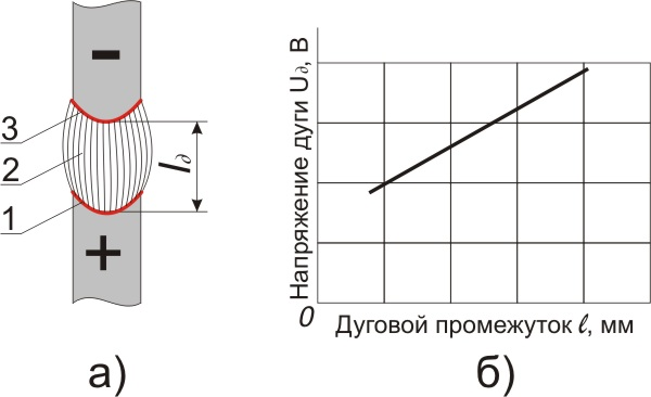
Rice. 1. Welding arc burning between non-consumable electrodes: a - arc diagram, b - dependence of arc voltage (Ud) on the value of the arc gap (/d): 1 - anode region, 2 - cathode region, 3 - arc column
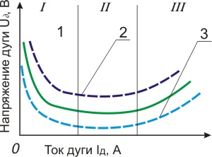
Fig.2 Volt-ampere characteristic of the arc (CVC)
This relatively high voltage is applied to the winding closest to the bridge by conduction back through the load and induces a similar voltage in the other winding. thereby canceling the offset of the second bridge and turning it off. In addition, at the second bridge, its firing is reduced to the return of the pump or to the recovery state. thereby facilitating switching.
Full turn-on for switching is obtained by turning all thyristor switches into one bridge at the same time as the behavior of the high-frequency pulses. A spray-spray welding method in which primary input electrons are applied towards the workpiece and spray transfer occurs = while the leakage current exceeds the 4-inch transient current level.
Shown in fig. 2 volt-ampere characteristic of the arc was taken at a constant length of the welding arc. When welding with a consumable electrode, the length of the arc gap is continuously changing. In these cases, one should use the characteristics that determine the relationship between the voltage and arc current at a constant electrode wire feed rate (Fig. 3, curves 1 and 2). Each feed rate corresponds to a certain range of currents, at which the welding arc burns steadily and the electrode melts. In this case, with small changes in current, the voltage changes over a large range. This dependence is called the characteristic of stable operation. It, like the current-voltage characteristic, depends on the length of the electrode stick-out and the feed rate.
Obtaining a measure of the actual arc length. Predefined maximum and minimum lengths. Arc: measuring the actual length of an arc. E. lowering the welding current to a low value, at. When aerosol transfer does not occur. when the arc length reaches the maximum arc length due to burning welding electrode when the welding current was above the transition level, where the spray gear is automatically switched on and off to allow self-regulation of the arc length between the set maximum and minimum lengths regardless of the high value welding current circuits can be arbitrarily higher than the transition current level and does not depend on the wire feed speed, and therefore the low value of the controlled welding current level is arbitrarily low and also does not depend on the wire feed speed.
These patterns are valid for direct and alternating current, since the type of current does not affect the shape of the current-voltage characteristics of the electric arc. The shape of the characteristic is affected by the geometry and material of the electrodes, the cooling conditions of the arc column, and the nature of the medium in which the discharge occurs.
The stability of the welding arc and the welding mode depend on the conditions for the existence of the arc discharge and the properties, parameters of the power sources and the electrical circuit. The external characteristic of the power source (curve 3 in Fig. 3) is the dependence of the voltage at its terminals on the load current. The following external characteristics of power sources are distinguished (Fig. 4): falling 1, gently falling 6, rigid 5, increasing 3 and vertical 2. A power source with one or another external characteristic is selected depending on the welding method. The control device of each source gives a number of external characteristics ("family of characteristics"). The steady-state operating mode of the system: "welding arc - power source" is determined by the intersection point A of the external characteristic of the power source (1, 2, 3, 5 or 6) and the current-voltage characteristic 7 of the welding arc.
The arc welding control system of claim 2 further comprising inductive means connected between said switching means and said electrode for supplying welding current to. When said source is disconnected from the electrode. An arc welding control system that meets the requirements is designed to automatically adjust the power source that supplies the welding current to the arc containing.
Hour setpoint control means connected between said source and electrode for selecting the setpoint given by the given welding current at the given welding is voltage. The feedback circuit means responding to the actual voltage of the arc to maintain a given current through them when the length of the arc matches the set voltage.
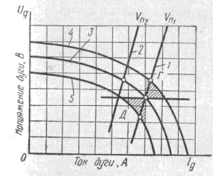
Fig.3 Current-voltage characteristic of the welding arc (CVC) 1.2 at a constant wire feed speed (characteristic of stable operation) and external characteristics of power sources 3, 4 and 5
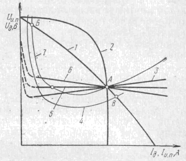
Fig.4 External characteristics of power sources 1, 2, 3, 5, 6 and current-voltage characteristics of the welding arc 4, 7
A bridge interruption circuit connected between the specified source and the welding electrode and including four semiconductor switches, a switching capacitor and a free wheel diode. The means associates said feedback circuit means with said bridge interrupt circuit.
A clamp diode connected between the junction of said commutating inductor coil and the high current inductive coil to prevent overvoltage applied to the high current inductor winding due to overvoltage of the source.
The welding process will be stable if for a long time the arc discharge exists continuously at the given values of voltage and current. As can be seen from fig. 4, at points A and B of the intersection of the external characteristics of the arc 7 and the power source, there will be an equilibrium in current and voltage. If for any reason the current in the welding arc corresponding to point A decreases, its voltage will be less than the steady value of the voltage of the power source; this will lead to an increase in current, i.e., to a return to point A. Conversely, with an accidental increase in current, the steady-state voltages of the power source turn out to be less than the arc voltage; this will lead to a decrease in current and, consequently, to the restoration of the welding arc burning mode. From similar reasoning it is clear that at point B the welding arc burns unsteadily. Any random changes in the current develop until it reaches a value corresponding to the point of stable equilibrium A or until the arc breaks. With a gently dipping external characteristic (curve 6), stable arcing will also occur at point A.
The welder control system according to claim 7, further comprising a logic circuit means for supplying gate pulses to selected semiconductor switches and means responsive to the voltage of the switching capacitor, and connected to said logic means for ensuring that gate pulses are applied to said switches only in a predetermined sequence determined by the magnitude and polarity of the capacitor voltage.
Arc welding control system - for use in the process arc welding with one spray, in which the welding electrode is continuously applied to the workpiece, and spray transfer occurs when the welding current exceeds the transient current level, and spray transfer does not occur when the welding current is at a "very low level" and contains. A. means for developing an arc length signal proportional to the actual arc length.
When working on a falling section of the current-voltage characteristic of the arc, the external characteristic of the source at the operating point must be more steeply falling than the static characteristic of the welding arc. With increasing arc characteristics, the external characteristics of the source can be hard 5 or even increasing 3.
At manual welding, when changes in the length of the arc are possible, it must have a sufficient margin of stability.
The means for comparing said arc length signal with the first and second signals proportional to a predetermined maximum and minimum are lengths. C. means associated with said comparison means for controlling the welding current to a high value above a specified transient current level when the actual arc length is reduced to a specified minimum arc length; as well as.
E. means associated with said comparison means for controlling the welding current to a low value such that no change in spray occurs when the arc length reaches a specified maximum arc length due to welding electrode burn when the welding current is above a specified transition level; whereby the spray transmission automatically turns on and off to self-adjust the arc length between the specified maximum and minimum lengths, regardless of the electrode feed speed, and wherein said high value of the controlled welding current can be arbitrarily higher than the specified transient current level and is independent of the wire feed speed and , therefore, the low value of the controlled level of the welding current is arbitrarily low and also does not depend on the wire feed speed.
Ceteris paribus, the stability margin increases with the increase in the steepness of the external characteristic of the power source. Therefore, sources with steeply falling characteristics are used for manual welding: the welder can lengthen the arc without fear that it will break, or shorten it without fear of an excessive increase in current.
Self-regulation of the welding arc. In automatic or semi-automatic consumable electrode welding, its feed rate (va) is equal to the melting rate. With an accidental decrease in the arc gap (curve 4 in Fig. 4), the current increases and the wire starts to melt faster. As a result, the arc gap will gradually increase and the welding arc will reach its original length. The same will happen with an accidental lengthening of the arc. This phenomenon is called self-regulation of the welding arc, since the restoration of the initial mode occurs without the influence of any regulator. Self-regulation is the more active, the more positive the external characteristic of the power source and the greater the electrode feed rate. Therefore, for mechanized consumable electrode welding, power sources with gently dipping external characteristics should be selected. When welding at direct current in shielding gases, when the static characteristic of the welding arc takes on an increasing form, it is rational to use sources with a rigid characteristic for self-regulation systems. However, their open-circuit voltage is low and may even be less than the working voltage of the arc, which makes it difficult to initially initiate it. In these cases, it is desirable to use power supplies with an external characteristic in the working part of a hard or gently increasing current-voltage characteristic, and the open-circuit voltage is slightly increased, as shown by the dotted line in Fig. 4.
Government support also includes matching funds from the Commonwealth of Kentucky. For a long time, traditional labor-intensive manual welding shows several disadvantages. One disadvantage of manual welding is that the quality of the welds is highly dependent on the skill of the welder. For the production of welded seams High Quality welders must receive intensive training and practical training, especially for intensive pipe welding. In such circumstances, it is desirable to encourage the introduction of automation technologies in the management of the welding process to assist welders by increasing their productivity. The gas tungsten arc welding process is commonly used in pipe welding. However, penetration control is highly dependent on the skill of the welder. When operating in keyhole greater penetration is achieved with reduced heat input. Although an automatic orbital welding system has been commercially available for many years, labor-intensive manual welding is still preferred. This is because the fully automatic process can easily be affected by small changes in process parameters and weld preparation and fit. However, intensive training and sufficient work experience are required before a welder can perform pipe welding and thus, there is a need for a control system that will solve this dilemma, assisting welders and compensating for their different skill levels. The arc voltage is monitored to determine when full penetration into the weld pool has occurred, the current to the welding torch can be reduced. It is understood that other embodiments of the present invention will become apparent to those skilled in the art from the following detailed description, in which only various embodiments of the invention are shown for purposes of illustration and description. As will be carried out, the invention is capable of performing other and various embodiments, and its several details can be modified in various other respects, all of which do not deviate from the essence and scope of the present invention. Accordingly, the drawings and the detailed description are to be considered as illustrative in nature and not as restrictive. Detailed description includes specific details in order to provide a thorough understanding of the invention. However, those skilled in the art will appreciate that the invention may be practiced without these specific details. In some cases, well-known structures and components are shown in block diagram form to avoid obscuring the concepts of the invention. In particular, its limited arc allows deeper penetration and reduces heat dissipation, heat affected area and distortion. This deeper penetration provides an excellent alternative to better provide full penetration for increased wall thickness. However, the restrained arc makes the molten metal weld pool dynamic and difficult to control in manual welding. The control method described below helps welders work during pipe welding by providing compensation appropriate to different skill levels. The results allow entry-level welders to produce acceptable welds, helping more welders with higher skill levels to produce more consistent welds despite minor work errors. The control system 100 may be based on an embedded controller, for example. It offers a complete control and communication solution for industrial applications. It provides 8 channels of 11-bit analog input and 2 channels of 12-bit analog output. As will be described in more detail later, the controller or control system 100 provides functional control signals 120 to the welding machine, current control signals 122 for the welding power source, and controls the arc voltage 124. To make the system transportable and rugged, the controller 100 can be assembled by integrating all components controller into a commercial equipment enclosure or similar enclosure. This unit integrates shielding gas, plasma gas and thermal water together into a compact power supply. For example, this torch is rated at 150 amps, but torches of other sizes can also be used. There is also a welding platform 206 along with other consumables that support the operation of the torch 204. In accordance with the principles of the present invention, two different penetration control algorithms can be implemented. Reference voltage method Since the arc voltage is proportional to the arc length at the same welding current, it is natural to measure the arc voltage to determine the arc length to control penetration. If the comparison is negative, it is considered that the desired full penetration has not been achieved. The sampling and comparison continues at steps 510 and 512. Otherwise, the current control signal returns to the base current to restart a new process period. One of ordinary skill will recognize that the parameters just described and the control system itself depend on the material to be welded, the thickness of the material to be welded and other parameters. environment . However, for a specific example, the following exemplary environment of one use of the control system is described. In general, the method described above uses the original weld pool surface as the reference surface and then determines weld penetration based on the deviation of the developing pool surface seam from the reference surface. In other words, the arc voltage is an indication of the length of the arc, and if the torch is held at nearly the same distance from the surface of the workpiece, then the length of the arc indicates how deep the pool penetrates into the workpiece. Thus, the difference in arc voltage across the bearing surface, and the arc voltage at a point in time, is an indication of how deep the penetration of the weld pool is. Weld Pool Bottom Detection Method The voltage reference method described above attempts to establish a flat reference on top of the weld pool 404 surface and use it to represent the workpiece surface. The required surface depth of the weld surface is measured from the surface of the workpiece. The method of detecting the bottom layer of the weld to be described can, under certain conditions, provide a more reliable and reliable method using the rate of change of the surface of the weld to facilitate control of the operation of the weld. Observation of experiments indicates that the arc voltage tends to stop or slow its rate of increase or even decrease slightly during the current peak period after some period of significant increase. This means that the length of the arc, that is, the distance from the torch 408 to the weld pool surface 404, is impregnated. Perhaps this was caused by the surface of the welded formation, the depth of which was saturated. If the surface of the weld has been saturated and does not develop further, a keyhole may be installed. Thus, the slope of the arc voltage can be used to determine whether the weld surface has reached the bottom of the workpiece. If achieved, full penetration is established. In this method, the base period 602 plays the same role as in the voltage reference method. In each peak period, a minimum peak time of 604 peaks is applied to ensure that any short term weld pool transient effects do not affect the control system. In each control period of 10 ms, the average of 10 arc voltage measurements is calculated to represent the peak voltage during that period. Compared with the reference voltage method, this method can better detect the occurrence of a keyhole and thus can create stronger welds and penetrate. In particular, current pulses are applied to the feed of the welding machine, so that the torch creates an arc that allows the formation of a weld. Thereafter, at step 704, the peak current is applied and, as shown at step 706, the peak current is applied for at least a minimum period of time. Once this minimum time has elapsed, the arc voltage is then sampled at step 708. In particular, the arc voltage may be sampled several times over a period of 10 ms, and then averaged samples to determine the value of this parameter. Next, at step 710, the slope of the increase in arc voltage is determined. One way to do this is to consider a moving window of four sampling periods. For each such window, the first value for the arc voltage and the third value for the arc voltage are compared in such a way as to determine the slope between them. Before running the algorithm, a keyhole criterion was defined that indicates the slope at which a keyhole condition is likely to occur at the weld site. If the calculated slope is less than this keyhole criterion, then a keyhole has likely occurred and welding can be stopped. If the calculated slope is higher than the keyhole criterion, then the peak current continues to be applied and the arc voltage continues to be sampled and monitored. For example, more than one or two determinations that the calculated slope is below a predetermined threshold may be required before the control algorithm stops the peak period at 718. Once the peak period is stopped, a determination is made at 720 if the welding process is complete. As discussed above, the current for the welding process occurs in pulses and subsequent pulses are activated until the welding process is completed. Although not shown in the algorithm, a maximum peak time period can be used to ensure that the weld stops even if the keyhole criterion is not met. In general, the method described above recognizes that the arc voltage does not increase at a high rate when the weld pool reaches the bottom of the workpiece at the welding site. Thus, when a keyhole condition occurs, the slope of the arc voltage approaches substantially zero. By determining when this happens, the control algorithm can stop the application of the peak current to the welding torch. In this method, the arc voltage slope indicates the rate at which the weld manifold develops. Based on the design of the weld pool surface, a determination can be made regarding the proximity of the weld surface to the bottom surface of the workpiece. As noted above, the choice of the keyhole criterion and some other parameters allows the control algorithm to provide quality welds. Below is an example of using stainless steel as a welding material. However, one of the ordinary experts will learn how to choose the right criterion and parameters for other metals and other welding situations. Thus, the specific values given below are for example purposes, and other values may be used without departing from the scope of the present invention. The bottom surface detection method was used to conduct a series of experiments. A square butt joint was prepared with no gap between the two pieces of pipe. When welding, the welding machine must maintain a constant distance and keep the flame perpendicular to the path of the weld. In order for the flame to move, the welder must hold the flame stopped during the peak period for the plasma arc to develop full penetration. Especially in manual welding, even a highly skilled pipe welder usually cannot keep the torch as stable as an orbital system. Due to the movement of the hand, several factors can appear, and these factors have more or less influence on the welding process. This section lists some influences as well as possible solutions to avoid defects in the welding process. In other words, the basic control algorithms described above can be supplemented by adding other parameters, as well as by determining the values of the control current. Linear travel speed. Linear motion speed directly controls the heat input and changes the arc current requirements. If the travel speed changes, the welding current must be changed to maintain the same heat input. When the welding current is set, changes in travel speed directly affect the heat input. The control algorithm can compensate to some extent for the change in travel speed, so the welder is advised to keep the travel speed in the proper range. The control algorithm measures the surface depth of the welding pool. If the flame is not perpendicular to the weld surface, the resulting deformation of the weld surface under arc pressure may change. If the deformation is changed, the measurement result may be different. As the torch moves around the pipe, the welding parameters may need to be changed to obtain the same weld penetration. For this control system, the density of the weld pool can affect the relationship between the depth of the weld surface and the penetration of the weld. Thus, a positioning method can also be included in the system to provide appropriate welding parameters for measurement. welding position in real time. Ideally, the flame should always be perpendicular to the surface of the weld. Thus, the 3D orientation changes over time for both the flame and the weld pool. Consequently, gravity will pull the molten metal inside the weld pool in different directions. Given the strong influence of welding position and speed on weld quality, both of these parameters can be controlled. In addition, since both parameters have a direct or indirect relation to gravity, it is also useful to use gravity sensitivity or acceleration. For example, as an acceleration sensor, for example, a three-second small-sized accelerometer with a small size of 0.8g ~ 6g can be used, although other sensors can be used. Since the flame 802 is always vertical to the weld surface and does not deviate beyond the plane of travel, the acceleration along the x-axis will be about 0, except for some error in operation. These two components show a sinusoidal change over time during the welding process. Further analysis of the data is required to obtain the actual position of the plume. When formulating the algorithm, numerous experiments are needed to determine the optimal parameters in these three positions. For areas from -90° to 0° and from 0° to 90°, linear interpolation was calculated to determine the correct parameters at one point. With the right parameters for each point around the entire circumference of the pipe joint, a base of good weld quality can be achieved. Obviously, the small sections will have the same length. Under this assumption, the three-dimensional orientation of the accelerometer gradually changes with respect to the direction of gravity. Approximate local gravitational acceleration is needed to convert the value of the sampled voltage to the actual acceleration. For any welding position, once the movement is pulsating, the welding speed can be calculated using the algorithm above. Although more complex and more accurate algorithms are available, the minimum amount of computation is preferred for this embedded system process controller, and the simple algorithm introduced above has proven to be effective. During operation, the above-described welding control system allows manual welding work, which can compensate for the experience of the welder by detecting the penetration depth of the weld automatically and adjusting the welding parameters accordingly. In the above description, there is a discussion that the current is applied in the welding process. One common skill is to recognize that the control systems and methods described herein can implement the application of current in several different ways without departing from the scope of the present invention. the control system may include a power supply so that it applies its own current. Alternatively, the control system may generate a control signal that controls a separate power supply to provide the appropriate current. In either case, the control system makes the determination when and how the current is applied to the welding torch to carry out the welding process. a description is given to enable any person skilled in the art to practice the various embodiments described herein. Various modifications to these embodiments will be apparent to those skilled in the art, and general principles defined here may be applied to other embodiments. Thus, the claims should not be limited to the embodiments shown here, but should be given in their entirety, consistent with the language of each application, and reference to an element in the singular does not mean one and only one Unless specifically stated specifically, but "one or several". All structural and functional equivalents of the elements of the various embodiments described throughout this specification, which are known or later known to those skilled in the art, are herein by reference and are intended to be covered by the claims. In addition, nothing disclosed herein is intended for the public, whether or not that disclosure is expressly stated in the claims. The government has certain rights in the invention. . This is a process that provides precise control of welding heat and is therefore commonly used for welding thin base metal and root pass deposition of thicker sectional welds.
The AC welding arc requires power sources to reliably re-ignite the welding arc. This is achieved the right choice relationships between open circuit voltages, ignition and arcing voltages and parameters of the welding circuit. The easiest way to obtain a stable welding arc is to include reactance in the welding circuit. Due to this, at the moment of re-ignition of the arc, the voltage on the arc can increase sharply (Fig. 5) to the value of the ignition voltage (U3). The dotted curve t/xx represents the voltage of the power supply at no load. Under load, due to the presence of reactance, the welding current lags behind the voltage in time.
When the arc breaks, the voltage across the arc gap should rise to a value corresponding to the instantaneous value of the open-circuit voltage of the power source. Due to the current lagging behind the voltage, this voltage is sufficient to re-ignite the welding arc (Un).
Metal transfer in the welding arc and requirements for the dynamic properties of power sources. There are the following types of transfer of the electrode metal into the weld pool: large-drop, characteristic of low current densities; small-drop, jet, when the metal flows from the electrode in very small drops. Drops of molten metal periodically close the arc gap, or if short circuits do not occur, periodically change the length of the arc. At a high current density in the electrode, small-drop metal transfer is observed, without noticeable fluctuations in the length and voltage of the welding arc.
Voltage, current and arc length undergo periodic changes from idle to short circuit; in the operating mode, the arc burns, the formation and growth of a drop occurs. In the future, with a short circuit between the drop and the bath, the current increases sharply. This leads to compression of the drop and destruction of the bridge between the drop and the electrode. The voltage increases almost instantly and the welding arc is re-ignited, i.e. the process is periodically repeated. The change of modes occurs within fractions of a second. Therefore, the power source must have high dynamic properties, i.e., a high rate of voltage increase when the circuit is broken and the desired rate of current rise.
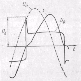
Rice. 5 Oscillogram of arc current and voltage during AC welding.
At a low rate of current rise, unmelted wire enters the bath. It warms up relatively slowly over a large area, which is then destroyed. If the current rises too quickly, the bridge between the bath and the drop of electrode metal quickly overheats and explodes. Part of the molten metal splashes and does not fall into the seam.
To avoid spatter, it is necessary to increase the electromagnetic inertia of the power source by increasing the inductance of the welding circuit.