Weld seam definition classification. Classification of welds and joints
The effectiveness and quality of work depends on the availability of the necessary tools, materials and skills. Knowledge of theory also significantly affects success in any business, no matter what direction it is. considered to be one of the most common.
This type of activity requires material, equipment, work experience, as well as theoretical knowledge. Having mastered the necessary information, a person gets an idea of \u200b\u200bwhat a seam is, what classification exists welds and how to choose the best option for coupling various metal products.
What is a weld seam?
During welding work three metal sections are involved in the process: with the help of the third, which acts as an electrode, two pieces of iron are fastened together. At the junction of metal parts with each other, a thermal process occurs, forming a seam. Thus, a seam is a part obtained as a result of the action of fused and solidified iron.

Any metal can be joined by welding. They have their own structural features, according to which a certain type of fastening is selected. Classification is made depending on the type of clutch, material and other parameters. Each connection has its own instructions and its own execution order.
Dimensions
There is a classification of welds by length. Depending on the size, there are:
- Short. The size does not exceed 30 cm. Such a seam appears as a result of welding performed in one direction from the very beginning to the end.
- Medium. Seam length - from 30 cm to 1 meter. These seams are welded from the middle to the edges. For them, the reverse-step method is ideal. Its essence lies in the fact that the entire seam is divided into several sections, which are alternately processed by welding. Each of these segments has a length of 10 to 30 cm.
- Long (over one meter). They are welded in the same way as the middle seams, with the only difference being that the number of sections here will be greater.
Types of welded joints
The classification of welds is also carried out according to the type of fastening. There are four types of connections:
- butt;
- tee;
- overlap;
- angular.
The most common type
During butt bonding, the thickness of the product is taken into account. This allows you to save a significant part of the material.

Butt clutch is considered the most popular. This is due to the fact that this welding process is the fastest and most economical.
This type of coupling is characterized by a T-shaped connection of metal products. As in the butt joint, Special attention is given to the thickness of the metal, depending on which the seams are one-sided and two-sided.

When applying this type of clutch, you must adhere to the following recommendations:
- When performing T-welding when joining two products with different thicknesses, it is necessary to keep the welding torch in relation to the thicker product at an angle of 60 degrees.
- Welding work can be facilitated by placing the structure "in the boat". This position of the workpiece will exclude undercuts, missing undercooked areas, which are considered the most common defects for this type of adhesion.
- If one pass of the welding torch turns out to be ineffective, since defective areas may remain, they should be welded by vibrating the welding electrodes.
- In a T-joint, one-sided welding can also be limited. To do this, you need to use the Oineo Tronic Pulse welding equipment, which allows RW brewing.
Overlap welding
The principle of this type of connection is the double-sided welding of products, the thickness of which is not more than 1 cm. This welding is used in cases where it is necessary to prevent moisture from entering the gap between the steel sheets. As a result of this work, two seams are formed. This type welded joint considered to be lengthy and not economical as it requires more materials to work.

Angular grip
This type of welding is used to connect metal products in a position perpendicular to each other. Depending on the thickness of the sheets, corner welding is characterized by the presence or absence of beveled edges. If necessary, this is done from the inside of the product.

Weld Shapes
The classification of welds according to the shape of the outer surface defines three types:
- Flat. They are effective under dynamic and alternating loads, since these seams (like concave ones) do not have a stress concentration that can cause sharp drops and destroy the welding bond.
- Concave. The concavity of the weld, not exceeding 0.3 cm, is considered acceptable. Otherwise, the concavity of the weld is considered excessive and is regarded as a defect. The level of concavity is measured in the area where there is the greatest deflection.
- Raised seams. Occurs as a result of accumulation a large number solidified metal and are considered uneconomical. But at the same time, a convex weld is more effective under static load than a flat or concave weld. The convexity index is the distance from the surface of the base metal to the point of greatest protrusion. Bulges not exceeding 0.2 cm for bottom welding and not more than 0.3 cm for welding made in other positions are considered standard.
Classification of welds by position in space
According to the criterion of placement in space, there are four types of welds, each of which has its own characteristics and recommendations for welding:
- bottom seams. In a technical aspect, they are considered the simplest. Welding of the lower seams is carried out on a flat surface in the position from below. This process is characterized by high efficiency and quality. This is due to more comfortable conditions for the welder. The molten metal is directed by its weight into a welded pool located in a horizontal position. It is easy to follow the cooking of the bottom seams. The work is done quickly.
- horizontal seams. Welding is a little more difficult. The problem is that the melted metal, under the influence of its weight, flows to the lower edges. This may result in undercuts at the top edge.
- vertical seams. They are the result of joints of metal products placed in a vertical plane.
- Ceiling seams. This welding considered the most difficult and responsible. It is characterized by minimal comfort. During the welding process, the release of slags and gases becomes more difficult. Not everyone can cope with this business, a lot of experience is needed, since it is not easy to keep slag falling on your face during work. It is important to observe the quality and strength of the connection.
How are welds and joints identified?
The classification and designation of welds is carried out using special icons, lines and callouts. They are placed on and on the structure itself. The classification of welded joints and seams is indicated, according to the regulatory document, using special lines that can be solid or dashed. Visible welds are indicated by solid lines, invisible ones by dashed lines.
Symbols of the seam are placed on the shelf from the callout (if the seam is located on the front part). Or, conversely, under the shelf, if the seam is placed with reverse side. With the help of icons, the classification of welds, their discontinuity, and the placement of segments for welding are indicated.
Next to the main icons are additional ones. They contain supporting information:
- on the removal of reinforcement of the weld;
- about surface treatment for a smooth transition to the base metal and the prevention of sags and irregularities;
- about the line along which the seam is made (whether it is closed).
For identical designs and products of the same GOST, standard symbols and technical requirements are provided. If there are identical seams in the structure, then it is better to give them serial numbers and divide them into groups, which are also assigned numbers for convenience. All information about the number of groups and seams should be indicated in the regulatory document.
seam position
Classification of welds is based on the position of the weld. They are:
- Unilateral. They are formed as a result of welding sheets, the thickness of which does not exceed 0.4 cm.
- Bilateral. Occurs during double-sided welding of metal sheets with a thickness of 0.8 cm. For each connection, it is recommended to leave 2 mm gaps to ensure adhesion quality.
Possible flaws
Defects during welding can occur due to excessive current and arc voltages. It can also be the result of improper manipulation of the electrodes. Classification of defects in welds according to their location:
- Internal. To identify them, a technique is used, which consists in control: not destroying the structure, destroying completely or partially.
- Outdoor. They are easily identified by external examination.
Due to a violation of the welding regime caused by a lack of necessary experience, insufficient preparatory work, and incorrect measurements, defects are divided into:
- Lack of fusion It manifests itself in the local absence of fusions between the connected elements. The defect leads to an increase in stress concentration and a decrease in the cross section of the weld. A design with such a flaw is characterized by reduced strength and reliability. The cause of lack of fusion can be both insufficient current strength and welding in fast mode.
- Undercut The defect consists in a local decrease in the thickness of the base metal. This problem observed near the boundaries of welds.
- Burnout. The flaw looks like a cavity in the weld. It occurs due to leakage of molten metal from the weld pool. A burn is an unacceptable defect, it must be urgently corrected.
- Unfilled crater or depression. It occurs due to arc breaks during the approach to the end of the seam.
- Influx The defect manifests itself in the leakage of the weld metal onto the base metal without their fusion.

The causes of defects can be very different, but they are equally capable of reducing adhesion strength, operational reliability, accuracy and spoiling the appearance of the product.
Terms and definitions for welded structures, assemblies, joints and seams are established by GOST 2601-84.
A welded joint is a permanent connection of two or more elements (parts) made by welding. A welded joint includes a weld, an adjacent area of the base metal with structural and other changes as a result of the thermal action of welding (the heat-affected zone) and areas of the base metal adjacent to it.
A weld is a section of a welded joint resulting from the crystallization of molten metal or as a result of plastic deformation during pressure welding, or a combination of crystallization and deformation.
A welded assembly is a part of a welded structure in which elements adjacent to each other are welded.
A welded structure is a metal structure made from individual parts or assemblies by welding.
The metal of the parts to be joined by welding is called the base metal.
The metal supplied to the arc zone in addition to the molten base metal is called filler metal.
The remelted filler metal introduced into the weld pool or welded onto the base metal is called weld metal.
The alloy formed by the remelted base or base and deposited metals is called the weld metal.
The performance of a welded product is determined by the type of welded joint, the shape and size of welded joints and seams, their location relative to the acting forces, the smoothness of the transition from the weld to the base metal, etc.
When choosing the type of welded joint, the operating conditions (static or dynamic loads), the method and conditions for the manufacture of the welded structure (manual welding, automatic welding in factory or installation conditions), savings in the base metal, electrodes, etc. are taken into account.
Types of welded joints. According to the form of conjugation of the parts (elements) to be joined, the following types of welded joints are distinguished: butt, corner, tee, lap (Figure 1).
Welds are subdivided according to the cross-sectional shape into butt (Figure 2, a) and fillet (Figure 2, b). A variation of these types are cork seams (Figure 2, c) and slotted seams (Figure 2, d), performed in overlap joints. According to the shape in the longitudinal direction, continuous and intermittent seams are distinguished.
Butt joints are mainly formed with the help of butt welds (Figure 1, a), with the help of fillet welds - tee, cross, corner and lap joints (Figure 1, b-d), with the help of cork and slotted joints, lap and sometimes tee connections.
Butt welds, as a rule, are continuous; a distinctive feature for them is usually the shape of the cutting edges of the parts to be joined in cross section. On this basis, the following main types of butt welds are distinguished: with edge flanging (Figure 3, a); without cutting edges - one-sided and two-sided (Figure 3, b); with cutting one edge - one-sided, two-sided; with a rectilinear or curvilinear form of cutting (Figure 3, c); with one-sided cutting of two edges; with V-shaped cutting (Figure 3, d); with bilateral cutting of two edges; X-shaped cutting (Figure 3, e). The groove can be formed by straight lines (beveled edges) or have a curvilinear shape (U-shaped groove, Figure 3, e).
a) butt; b, c) tee; d) angular; e) lap
Picture 1 - The main types of welded joints

a) butt; b) corner; c) cork; d) slotted
Picture 2 - The main types of welds
The butt joint is most common in welded structures, since it has a number of advantages over other types of joints. It is used in a wide range of thicknesses of welded parts from tenths of a millimeter to hundreds of millimeters in almost all welding methods. With a butt joint, less filler material is consumed for the formation of a seam, it is easy and convenient to control the quality.

a) with flanging edges; b) without cutting edges;
c, d, e, f) with grooved edges
Picture 3 - Preparation of the edges of the butt welds
Fillet welds are distinguished by the shape of the preparation of the edges to be welded in cross section and the continuity of the weld along the length.
According to the cross-sectional shape, fillet welds can be without cutting edges (Figure 4, a), with one-sided cutting of edges (Figure 4, b), with two-sided cutting of edges (Figure 4, c). In terms of length, fillet welds can be continuous (Figure 5, a) and intermittent (Figure 5, b), with a staggered (Figure 5, c) and chain (Figure 5, d) arrangement of weld segments. T-joints, lap joints and corner joints can be made with segments of seams of small length - spot seams (Figure 5, e).
Cork seams in their shape in plan (top view) usually have a round shape and are obtained as a result of complete penetration of the upper and partial penetration of the lower sheets (Figure 6, a) - they are often called electric rivets, or by melting the top sheet through a previously made in the top sheet hole (Figure 6, b).

a) without cutting edges; b, c) with cutting edge
Figure 4 - Preparation of the edges of fillet welds tee
compounds
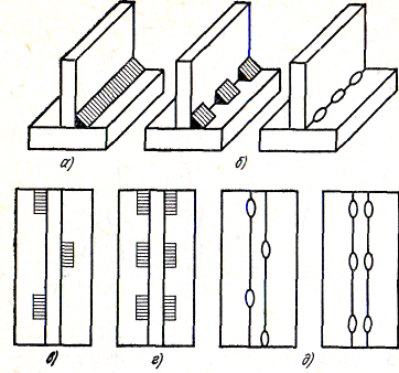
Figure 5 - Fillet welds of tee joints
Figure 6 - Cross-sectional shape of cork and
welt seams
Slotted seams, usually of an elongated shape, are obtained by welding the upper (covering) sheet to the lower fillet weld along the perimeter of the slot (Figure 6, c). In some cases, the slot can be filled completely.
The form of cutting edges and their assembly for welding is characterized by four main structural elements (Figure 7): gap b, blunt c, bevel angle  and bevel angle
  , equal to or 2 .
Existing methods of arc welding without cutting edges allow welding metal of limited thickness (with one-sided manual welding - up to 4 mm, mechanized submerged arc welding - up to 18 mm). Therefore, when welding thick metal, it is necessary to cut the edges. The bevel angle of the edge provides a certain value of the angle of cutting the edges, which is necessary for the access of the arc deep into the joint and complete penetration of the edges through their entire thickness.
The standard angle of cutting edges, depending on the method of welding and the type of connection, varies from 60 ± 5 to 20 ± 5 degrees. The type of groove and the value of the groove angle determine the amount of additional metal required to fill the groove, and hence the welding productivity. So, for example, the X-shaped groove in comparison with the V-shaped one allows to reduce the volume of deposited metal by 1.6-1.7 times. Reduced edge processing time. True, in this case, it becomes necessary to weld on one side of the seam in an uncomfortable overhead position or turn over the products to be welded.
Dullness c is usually 2 ± 1 mm. Its purpose is to ensure proper formation and prevent burns at the top of the seam. The gap b is usually equal to 1.5-2 mm, since at the accepted angles of cutting the edges, the presence of a gap is necessary for penetration of the weld top, but in some cases, with a particular technology, the gap can be zero or reach 8-10 mm or more.
For all types of seams, the complete penetration of the edges of the elements to be joined and the external shape of the seam both on the front side (reinforcement of the seam) and on the back side, i.e. the shape of the reverse roller, are important. In butt, especially one-sided welds, it is difficult to weld the blunting edges to their full thickness without special techniques that prevent burn-through and ensure good formation of the back bead.

Figure 7 - Structural elements of cutting edges and
assemblies for welding
Welds are classified according to a number of criteria. In appearance, the seams are divided into convex, normal, concave (Figure 8). As a rule, everything
seams are performed with a slight increase (convex). If non-reinforced joints are required, this should be indicated on the drawing. Weakened (concave) fillet welds are performed, which is also noted in the drawing. Such seams are required to improve the performance of welded joints, for example, under variable loads. Butt welds are not weakened, concavity in this case is a marriage. An increase in the size of welds compared to the specified ones leads to an increase in the mass of the welded structure and excessive consumption of electrodes. As a result, the cost of welded structures increases, the labor intensity of welding operations increases.

a) convex; b) normal; c) concave
Figure 8 - Classification of seams in appearance
The formation of a smooth transition of the metal of the front and back beads to the base metal is also of great importance, since this ensures high joint strength under dynamic loads. In fillet welds, it can also be difficult to weld the root of the weld through its entire thickness, especially when welding with an inclined electrode. For these welds, a concave cross-sectional shape of the weld with a smooth transition to the base metal is recommended, which reduces the stress concentration at the transition point and increases the strength of the joint under dynamic loads.
By the number of layers and passes, single-layer, multi-layer, single-pass, multi-pass seams are distinguished (Figure 9, 10).
Weld layer - part of the weld metal, which consists of one or more beads located at the same level of the cross section of the weld. Bead - weld metal deposited or remelted in one pass.

Figure 9 - Classification of seams according to performance: a - one-sided; b - bilateral

Figure 10 - Classification of seams according to the number of layers and passes:
I-IV - number of layers; 1~8 - number of passes
When welding, each layer of a multilayer weld is annealed when the next layer is applied. As a result of such a thermal effect on the weld metal, its structure and mechanical properties are improved. The thickness of each layer in multilayer joints is approximately 5-6 mm.
According to the acting force, the seams are divided into longitudinal (flank), transverse (frontal), combined, oblique (Figure 11). The frontal seam is located perpendicular to the force P, the flank seam is parallel, and the oblique seam is at an angle.
By position in space, lower, horizontal, vertical and ceiling seams are distinguished (Figure 12). They differ from each other in the angles at which the surface of the welded part is located relative to the horizontal. The ceiling seam is the most difficult to perform, the seam is best formed in the lower position. Ceiling, vertical and horizontal seams usually have to be performed during the manufacture and, especially, during the installation of large-sized structures.

a) - longitudinal (flank); b) - transverse (frontal);
c) - combined; d) - oblique
Figure 11 - Classification of seams according to the acting force

Figure 12 - Classification of welds according to their position
in space
Examples of the designation of welds according to their position in space are given in Figure 13

H - lower; P - ceiling; Pp - semi-ceiling; G - horizontal;
PV - semi-vertical; B - vertical; L - in the boat;
Pg - semi-horizontal
Figure 13 - Designation of welds by their position
1. Introduction............................................... ................................................. ............................... 2
2. Main types of welded joints .............................................. ................................... 3
3. Classification of welds .............................................................. ............................................. 7
4. Structural elements of welded joints .............................................. ................fourteen
5. Conclusion ............................................... ................................................. ........................ 15
6. Labor protection ……………………………………………………………………………... 19
7. Environmental part …………………………………………………………………….. 20
8. Literature ……………………………………………………………………………….. 21
Introduction
Welding is a technological process of obtaining permanent joints of materials by establishing interatomic bonds between the parts to be welded during their local or plastic deformation, or by the combined action of both. Welding connects homogeneous and dissimilar metals and their alloys, metals with some non-metallic materials (ceramics, graphite, glass, etc.), as well as plastics.
Welding is a cost-effective, high-performance and largely mechanized technological process that is widely used in almost all branches of engineering.
The physical essence of the welding process is the formation of strong bonds between atoms and molecules on the joined surfaces of the workpieces. For the formation of joints, the following conditions must be met: the surfaces to be welded must be free from contaminants, oxides, and foreign atoms adsorbed on them; energy activation of surface atoms, facilitating their interaction with each other; convergence of the welded surfaces at distances comparable to the interatomic distance in the workpieces to be welded.
Depending on the form of energy used to form a welded joint, all types of welding are divided into three classes: thermal, thermomechanical and mechanical.
The thermal class includes types of welding carried out by melting using thermal energy (arc, plasma, electroslag, electron beam, laser, gas, etc.).
The thermomechanical class includes types of welding carried out using thermal energy and pressure (contact, diffusion, etc.).
The mechanical class includes the types of welding carried out using mechanical energy and pressure (ultrasonic, explosion, friction, cold, etc.).
Weldability is the property of a metal or a combination of metals to form, with the established welding technology, a joint that meets the requirements determined by the design and operation of the product.
Most metal structures consist of individual elements connected to each other. Connections can be movable and fixed, detachable and one-piece. Permanent connections of metal elements in modern conditions are carried out by welding, soldering, riveting and gluing. The most advanced types of joints of metal elements are welded and soldered. In these cases, a metallic form of bond appears between the connected elements. Welding and soldering are very ancient processes. However, only at the end of the 18th century did the rapid development of welding begin, associated with the intensive development of industry. It should be noted that the development and practical use the main modern methods of welding were carried out in those days by wonderful Russian engineers and.
Welding metallurgy is different from other metallurgical processes high temperatures thermal cycle and a short lifetime of the weld pool in the liquid state, i.e., in a state accessible for metallurgical processing of the weld metal. In addition, the processes of crystallization of the weld pool, starting from the fusion boundary, and the formation of a heat-affected zone of metal changed in its properties are specific.
Main types of welded joints
Welded is an integral connection of several parts obtained by welding. Depending on the relative position of the welded elements in space, there are several types of welded joints.
The butt joint is most suitable for the specifics of welding and provides optimal conditions for the transfer of forces from one element to another. This type of connection can be formed by elements of the same (Fig. 1, a) and different thicknesses (Fig. 1, b). The thickness of the metal is not limited. A variation is a connection with a flanging of the edges (Fig. 1, c), used for metal up to 3 mm thick. In gas welding of metal up to 2 mm thick, the butt joint is performed without cutting edges and without a gap or with flanging of edges without filler metal. With a metal thickness of 2-5 mm, butt joints are carried out without cutting edges with a gap, with a thickness of more than 5 mm - with cutting edges (with a thickness of 5-15 mm - V-shaped cutting, more than 15 mm - X-shaped cutting).
1. Butt joint of elements to be welded
a- the same thickness; b - different thicknesses; e - with flanging
T-joint. The angle between the shelf and the wall can be straight (Fig. 2a), acute or obtuse. The tee joint is used when welding stiffeners, pipe couplings, scarves.
Lap connection (Fig. 2.6) is a package of two metal elements up to 20 mm thick. This type of connection does not require special precision of workpieces; for metal up to 4 mm thick, it does not require edge processing either. However, the lap joint creates unfavorable conditions for the transmission of forces due to the bending moment resulting from misalignment of the load application, low endurance limit, increased metal consumption and long weld lengths. When welding metal with a thickness of more than 3 mm, it is undesirable to use lap joints, since significant deformations occur due to high self-stresses, which, when rigidly fastened, can lead to cracks.
Gusset. The angle between the assembled elements can be straight (Fig. 2, c), acute or obtuse. Sometimes the connection shown in Fig. 2, city

2. T-joint (a), lap joint (b), corner joint (c), end-to-end (d)

3. Types of welds in relation to the acting force P
a - flank; b - frontal; c - combined; g - oblique

4. Classification of welds according to their location in space
a - lower; b - horizontal; c - vertical; g - ceiling

5. Classification of seams by shape
a - normal; b - reinforced; c - weakened
A weld is a section of a welded joint formed as a result of crystallization of the metal of the weld pool. The seam connecting the parts in a butt joint is called a butt joint, in a tee, corner and lap joint - a corner one. By the nature of the execution, the seams are one- and two-sided; in the direction of the acting forces - flank, frontal, combined and oblique (Fig. 3). In the flank seam, the acting force is directed parallel to the axis of the seam, in the frontal seam - perpendicularly, in the oblique - at an angle.

6. Cross section of the weld
Depending on the location in space, the seams are lower, vertical, horizontal and ceiling (Fig. 4). By length, continuous and intermittent seams are distinguished. The length of a separate segment of the intermittent seam is 50-150 mm, and the distance between them is 1.5-2.5 of the seam length. In external form, welds are normal, reinforced and weakened (Fig. 5). However, one should not think that reinforced seams are more durable than normal ones. At reinforced welds, it is impossible to ensure a smooth transition from the deposited metal to the base metal, and stresses are concentrated in these places, which can lead to the destruction of the welded product.
The absence of a gap also leads to lack of fusion, and the lack of dullness can cause burns. In gas welding, metal up to 5 mm thick is welded in one pass. For metal of large thicknesses, a special cutting of the edges is used, and welding is carried out in several passes.
Welding methods
The currently existing welding methods can be divided into two main groups (according to the state of the edges being joined during the welding process). The first group includes methods in which metals are welded in the solid state during joint plastic deformation, often simultaneously with additional heating (pressure welding methods). The second group includes methods in which metals are melted together (fusion welding methods).
When welding by the methods of the first group, the metals are jointly compressed and deformed. Depending on the temperature of the metal at the welding site, these methods are divided into three subgroups. In the first case, welding is carried out without heating the metals (deep deformation welding, shear welding). These methods weld only highly ductile metals. In the second case, metals are heated during welding to temperatures close to the temperature of the recrystallization threshold (welding with ultrasonic vibrations).
The methods of the third subgroup are of the greatest importance. Metals in this case are heated to temperatures significantly exceeding the temperature of the recrystallization threshold. As heat sources, a forge (forge welding), electric current (contact butt and seam-butt welding), gas flame (gas-pressure welding), etc. are used.
When welding by the methods of the second group, a pool of molten metal is created between the parts to be joined by a powerful heat source. It is formed mainly due to the melting of the edges of the parts to be welded. After removing the heat source in the bath, it hardens (crystallizes) and a welded joint is formed. As a heat source, an electric arc, electric current, electron flow, gas flame, etc. are used.
Types of welded joints
There are the following types of welded joints: butt, lap, corner and tee (butt).
Butt joints are called joints in which the elements are connected by ends or edges and one element is a continuation of the other. Butt joints are the most rational, as they have the lowest stress concentration during the transmission of forces, are economical and convenient for control. The thickness of the elements to be welded in joints of this type is almost unlimited. Sheet metal butt joints can be made with a straight or oblique seam. Butt joints of profile metal are used less frequently, since it is difficult to process their edges for welding.
Lap joints are those in which the surfaces of the elements to be welded partially overlap each other. These joints are widely used in welding sheet structures made of steel of small thickness (2-5 mm), in lattice and some other types of structures. A variety of lap joints are joints with overlays, which are used to connect elements of profile metal and to reinforce joints.
Sometimes the profile metal butt joint is reinforced with overlays, and then it is called combined.
Lap joints and overlays are distinguished by the ease of processing elements for welding, but in terms of metal consumption they are less economical than butt joints. In addition, these connections cause a sharp concentration of stresses, which is why they are undesirable in structures subjected to variable or dynamic loads and operating at low temperatures.
Corner joints are called joints in which the elements to be welded are located at an angle.
Tee joints (butt joints) differ from corner joints in that in them the end of one element is welded to the surface of another element. Corner and tee joints are made by fillet welds, are widely used in structures and are distinguished by their simplicity of execution, high strength and cost-effectiveness.
In critical structures, in tee joints (for example, in the seams of connecting the upper chord crane beam to the wall), complete penetration of the elements to be joined is desirable.
Classification of welds
Welds are classified according to the design feature, purpose, position, length and external shape.
By design, the seams are divided into butt and corner (roller). In table. 5.2 shows the types of seams and the necessary form of cutting the edges of the connected elements of various thicknesses to ensure a high-quality connection in automated and manual welding.
Butt welds are the most rational, as they have the lowest stress concentration, but they require additional cutting of the edges. When welding elements with a thickness of more than 8 mm, gaps and processing of the edges of the product are necessary to melt the metal through the entire thickness of the section. In accordance with the shape of the grooves, the seams are V, U, X and K-shaped. For V - and U-shaped welds welded on one side, it is obligatory to weld the root of the weld on the other side to eliminate possible lack of penetration, which is a source of stress concentration.
The beginning and end of the seam have lack of penetration and a crater, are defective and it is desirable to bring them to the technological strips outside the working section of the seam, and then cut them off.
In automatic welding, smaller sizes of cutting edges of the seams are accepted due to the greater penetration of the elements to be joined (Table 5.2). To ensure full penetration of the seam, one-sided automatic welding is often performed on a flux pad, on a copper backing, or on a steel remaining backing.
In electroslag welding, cutting the edges of the sheets is not required, but the gap in the joint is taken at least 14 mm.
Fillet (roller) seams are welded into a corner formed by "elements located in different planes. The cutting of the edges of the product used in this case is shown in Table 5.2.
Fillet welds located parallel to the acting axial force are called flank, and perpendicular to the force - frontal.
Seams can be working or connecting (constructive), continuous or intermittent (keyway). According to their position in space during their execution, they are lower, vertical, horizontal and ceiling. Welding of the lower seams is the most convenient, easy to mechanize, gives the best quality of the seam, and therefore, when designing, it should be possible to make most of the seams in the lower position. Vertical, horizontal and ceiling seams are mostly performed during installation. They are difficult to mechanize, it is difficult to perform them manually, the quality of the seam is worse, and therefore their use in structures should be limited as far as possible.
http://pandia.ru/text/79/352/images/image008_38.jpg" width="288" height="201 src=">
A welded joint as a structural element is a section of a structure in which its individual elements are connected by welding. A welded joint includes a weld, an adjacent area of the base metal with structural and other changes as a result of the thermal action of welding (the heat-affected zone) and areas of the base metal adjacent to it.
A weld is a crystallized metal that was in a molten state during the welding process.
The separation of these concepts is necessary because the weld, as a connecting part of the elements to be joined, determines geometric shape, continuity, strength and other properties of the metal directly at the welding site. The properties of a welded joint are determined by the properties of the metal of the weld itself and the base metal zone adjacent to the weld, with a modified structure and in many cases with modified properties - the heat-affected zone. It is also necessary to take into account some part of the base metal adjacent to the heat-affected zone and determining the stress concentration at the transition point from the weld metal to the base metal and plastic deformations in the heat-affected zone, which affects the nature and distribution of forces acting in the welded joint.
According to the shape of the conjugation of the welded elements, the following main types of welded joints can be distinguished: butt (Fig. 1, a), tee (Fig. 1, b and c), corner (Fig. 1, d), lap (Fig. 1, e) .
Welds are divided according to the shape of the cross section into butt (Fig. 2, a) and fillet (Fig. 2, b). A variation of these types are cork seams (Fig. 2, c) and slotted seams (Fig. 2, d), performed in overlap joints. According to the shape in the longitudinal direction, continuous and intermittent seams are distinguished.
With the help of butt welds, they mainly form butt joints (Fig. 1, a), with the help of fillet welds - tee, cross, corner and lap joints (Fig. 1, b-d), with the help of cork and slotted joints, lap joints can be formed and sometimes tee joints.
Butt welds, as a rule, are continuous; hallmark for them, the form of cutting the edges of the parts to be joined in cross section usually serves. On this basis, the following main types of butt welds are distinguished: with edge flanging (Fig. 3, a); without cutting edges - one-sided and two-sided (Fig. 3, b); with cutting one edge - one-sided, two-sided; with a rectilinear or curvilinear form of cutting (Fig. 3, f); with one-sided cutting of two edges; with V-shaped cutting (Fig. 3, d); with bilateral cutting of two edges; X-shaped cutting (Fig. 3, e). The groove can be formed by straight lines (beveled edges) or have a curvilinear shape (U-shaped groove, Fig. 3, e).
Fillet welds are distinguished by the shape of the preparation of the edges to be welded in cross section and the continuity of the weld along the length.
According to the shape of the cross section, the seams can be without cutting the edges (Fig. 4, a), with one-sided cutting of the edges (Fig. 4, b), with two-sided cutting of the edges (Fig. 4, c). In terms of length, fillet welds can be continuous (Fig. 5, a) and intermittent (Fig. 5, b), with a staggered (Fig. 5, c) and chain (Fig. 5, d) arrangement of weld segments. T-joints, lap joints and corner joints can be made with segments of seams of small length - spot seams (Fig. 5, e).
Cork seams in terms of their shape in plan (top view) usually have a round shape and are obtained as a result of complete penetration of the upper and partial penetration of the lower sheets - they are often called electric rivets, or by melting the top sheet through a hole previously made in the top sheet.
Slotted seams, usually of an elongated shape, are obtained by welding the top (covering) sheet to the bottom fillet weld along the perimeter of the slot. In some cases, the slot can be filled completely.
The shape of the groove and their assembly for welding is characterized by four main structural elements: gap b, bluntness c, bevel angle beta and groove angle alfa, equal to beta or 2 beta
Existing methods of arc welding without cutting edges allow welding metal of limited thickness with one-sided manual welding - up to 4 mm, mechanized submerged arc welding - up to 18 mm). Therefore, when welding thick metal, it is necessary to cut the edges. The bevel angle of the edge provides a certain value of the angle of cutting the edges, which is necessary for the access of the arc to the depth of the joint and complete penetration of the edges throughout their entire thickness.
The standard angle of cutting edges, depending on the method of welding and the type of connection, varies from 60 ± 5 to 20 ± 5 degrees. The type of groove and the value of the groove angle determine the amount of additional metal required to fill the groove, and hence the welding productivity. So, for example, the X-shaped groove in comparison with the V-shaped one allows to reduce the volume of deposited metal by 1.6-1.7 times. Reduced edge processing time. True, in this case, it becomes necessary to weld on one side 1va in an uncomfortable ceiling position or turn over the welded products.
Dullness c is usually 2 ± 1 mm. Its purpose is to ensure proper formation and prevent burns at the top of the seam. The gap b is usually equal to 1.5-2 mm, since at the accepted angles of cutting the edges, the presence of a gap is necessary for penetration of the weld top, but in some cases, with a particular technology, the gap can be zero or reach 8-10 mm or more.
For all types of seams, the complete penetration of the edges of the elements to be joined and the external shape of the seam both on the front side (the so-called seam reinforcement) and on the back side, i.e. the shape of the so-called reverse bead, are important. In butt, especially one-sided welds, it is difficult to weld the blunting edges to their full thickness without special techniques that prevent burn-through and ensure good formation of the back bead.
The formation of a smooth transition of the metal of the front and back rollers to the base metal is also important, since this ensures high joint strength under dynamic loads. In fillet welds, it is also difficult to weld the root of the weld over its entire thickness (see Fig. 1, b and c), especially when welding with an inclined electrode. For these welds, a concave cross-sectional shape of the weld with a smooth transition to the base metal is recommended, which reduces the stress concentration at the transition point and increases the strength of the joint under dynamic loads.
http://pandia.ru/text/79/352/images/image010_31.jpg" width="468" height="224 src=">
http://pandia.ru/text/79/352/images/image012_33.jpg" width="471" height="249 src=">
2.2. Classification of welds according to various external features
Welded seams of structures made of steel, non-ferrous metals and their alloys differ in a number of ways.
According to the position relative to the acting force R, the seams can be frontal, oblique and flank. These definitions apply to fillet welds in lap joints (2.7). The frontal seam is located perpendicular to the force, the flank seam is parallel, and the oblique seam is at an angle.
The separation of welds according to the main provisions of fusion welding was established by GOST 11969-79 *. According to GOST, the welding position is determined by the angle of inclination a of the longitudinal axis of the weld and the angle of rotation p of its transverse axis relative to their zero positions. If the individual layers of a multi-layer weld are made in different positions, the designations refer to each layer separately. In table. 2.1 shows diagrams various provisions and their designations. An arrow pointing up indicates welding on the rise, pointing down - welding on the descent. In terms of convenience and ease of implementation, the best position is L and N, then the positions become more difficult in this order: Pv, Pg, V, D, Pp and P> the last two are the most difficult to perform, they should be avoided.
Welds vary in their length and are continuous and intermittent. Basically, all seams are made continuous, however, intermittent seams are sometimes used if their continuity is not required and at low loads. When assembling structures for welding, assembly seams are often used - tacks that are placed intermittently to pre-fix the structures. Depending on the weight of the assembled elements and their thickness, the length and cross section of the tacks are assigned: the greater the weight and thickness, the more tacks should be. According to the external shape and the amount of deposited metal, convex and concave seams are distinguished (2.8). As a rule, all seams are made convex with a slight reinforcement, the nominal value of which is 0.5 mm, set by GOST 5264-80. Sometimes it is required to make seams without bulging, which should be indicated in the drawings. Concave fillet welds are performed, which is also indicated in the drawings and is required to improve the performance of welded joints under variable loads or for another reason. Butt seams are not made horned, the concavity of such seams is a marriage. Butt and fillet welds can be single-layer with a small thickness of the parts to be welded OR multi-layer (2.9) with a large thickness. Single-layer seams, as a rule, are single-pass, and multi-layer - multi-pass * By the nature of the requirements for welds, they can be strong or dense (impermeable to gases or liquids). As a rule, welded joints (especially butt joints) should be equal. Welds in appearance are divided into
normal (flat);
convex (reinforced);
concave (weakened).
Weld defects
The reliability of operation of welded joints depends on their compliance with the regulatory documentation that regulates constructive dimensions and the shape of finished welds, strength, ductility, corrosion resistance and properties of welded joints. All occurring types of defects in welded joints can be divided into four groups: by location, shape, size and quantity. By location, defects are distinguished external, internal and through. The shape is compact and extended, flat and voluminous, sharp (with a notch) and rounded (without a notch). Sizes are small, medium and large. By quantity - single and group (chains, clusters). External defects include violations of the shape, size and appearance seams: uneven width of the seam along its length, uneven height of the seam, uneven legs of fillet welds, undercuts, sagging, burns, not welded craters, fistulas. The formation of internal defects during welding is associated with metallurgical, thermal and hydrodynamic phenomena occurring during the formation of the weld. Internal defects include cracks (hot and cold), lack of penetration, pores, slag tungsten and oxide inclusions.
Lack of penetration is a section of a welded joint where there is no fusion between the parts to be welded, for example, at the root of the weld, between the base and deposited metal (along the edge) or between adjacent layers of deposited metal. Lack of penetration reduces the working section of the weld, which can lead to a decrease in the performance of the welded joint. Being stress concentrators, lack of penetration can cause cracks, reduce the corrosion resistance of the welded joint, and lead to corrosion cracking. Lack of fusion is a very dangerous welding defect.
Porosity - gas bubbles in the metal. Usually they have a spherical or close to it shape. IN welds In carbon steels, the pores are often tubular in shape. Initially, having arisen in the liquid weld metal due to intense gas formation, not all gas bubbles have time to rise to the surface and escape into the atmosphere. Some of them remain in the weld metal. The sizes of such pores vary from microscopic to 2–3 mm in diameter, and can grow due to diffusion of gases. In addition to single pores caused by the action of random factors, pores can appear in welds, evenly distributed over the entire weld cross section, arranged in the form of chains or individual clusters.
Cracks are defects in welds, which are macroscopic and macroscopic intercrystalline fractures that form cavities with a very small initial opening. Under the action of residual and working stresses, cracks can propagate at high speeds. Therefore, the brittle fractures caused by them occur almost instantly and are very dangerous.
Slag inclusions are cavities in the weld metal filled with slags that do not have time to float to the surface of the weld. Slag inclusions are formed at high welding speeds, with severe contamination of the edges and in multilayer welding in cases of poor cleaning of the surface of the seams between layers from slag. The shape of slag inclusions can be very diverse, as a result of which they are more dangerous defects than rounded pores.
Undercut - defects in a welded joint, which are local reductions in the thickness of the base metal in the form of grooves located along the boundaries of the weld. Undercuts are among the most common external defects, which are formed, as a rule, when welding fillet welds with an excessively high arc voltage and in case of inaccurate electrode guidance. One of the edges is melted more deeply, the metal flows down onto the horizontal part and there is not enough of it to fill the groove. Undercuts are less common in butt welds. Usually, with increased arc voltage and high welding speed, bilateral undercuts are formed. The same undercuts are also formed in the case of an increase in the angle of cutting during automatic welding.
Permissible and non-permissible defects
In fusion welding, defects are usually corrected by welding the defective spot. Before welding, the defective place must be cut so that it is convenient to weld. It is usually not allowed to correct the same place by welding more than two times in order to avoid overheating or overburning of the metal.
In spot welding, defects are corrected by setting a new point. In some cases, for example, in the case of a burn through, rivets are placed in a defective place.
The nature and number of defects allowed without correction should be indicated in the specifications for the welding or assembly.
Control
Depending on the nature of the impact on the material of the sample or product, all the various methods of quality control of welded joints can be divided into two main groups: testing methods without destroying samples or products - non-destructive testing and testing methods with the destruction of samples or production joints - destructive testing. A group of control methods, united by common physical characteristics, constitutes the type of control. All types of non-destructive testing are classified according to the following five main features: by the nature of the physical fields or radiation interacting with the controlled object; by the nature of the interaction of physical fields or substances with a controlled object; according to the primary informative parameters of the control methods under consideration; according to the methods of indication of primary information; on how to present the final information. All methods of non-destructive testing are divided according to the standard into the following ten types: acoustic, capillary, magnetic, optical, radiation, radio wave, thermal, leak detection, electric, electromagnetic (eddy currents). The most widely used in practice are the methods of five of them - acoustic, capillary, magnetic, radiation and leak detection.
The non-destructive types of control should also include control by external inspection and measurement, which is essential for obtaining high-quality welded structures.
Structural elements of welded joints
The form of cutting edges and their assembly for welding is characterized by three main structural elements: gap - in, blunting of edges - c, and bevel angle of the edge - p.
The type and angle of the groove determine the amount of electrode metal required to fill the groove, and hence the productivity of welding. X-shaped groove, in comparison with V-shaped, allows to reduce the volume of deposited metal by 1.6 - 1.7
times. In addition, this groove provides a smaller amount of deformation after welding. With X-shaped and V-shaped cutting, the edges are blunted for the correct formation of the seam and to prevent the formation of burns. The gap during assembly for welding is determined by the thickness of the metals being welded, the grade of material, the welding method, the shape of the edge preparation, etc. For example, the minimum gap is prescribed when welding without filler metal of small thicknesses (up to 2 mm) or when arc welding non-consumable electrode of aluminum alloys. When welding with a consumable electrode, the gap is usually 0 - 5 mm, an increase in the gap contributes to a deeper penetration of the metal.
The seam of the welded joint is characterized by the main structural elements in accordance with GOST 2601-84:
width - e, convexity - q, h - penetration depth (for a butt weld) and k - leg for a fillet weld; s - part thickness.
http://pandia.ru/text/79/352/images/image014_19.jpg" width="193 height=179" height="179">
http://pandia.ru/text/79/352/images/image016_10.jpg" width="187 height=92" height="92">
http://pandia.ru/text/79/352/images/image018_8.jpg" width="236" height="142 src=">
Conclusion
The quality of welded joints depends on the quality of the initial base and welding materials, the quality of the assembly for welding, adherence to welding technologies and other factors. The occurrence of defects is largely associated not only with technical, but also with organizational reasons. It follows from this that welding production technologists should not only know the defects of welded joints inherent in various welding methods, methods and equipment for their detection, but also be proficient in the organization of welding quality management. Leningrad. 1986 In my work, I reflected the essence of only the main and most general processes occurring in the metal during welding, although I tried to present them as detailed and interesting as possible.
Basic issues of welding.
Welding is accompanied by a complex of simultaneously occurring processes, the main of which are: thermal effect on the metal in the heat-affected zone, thermal deformation melting, metallurgical processing and crystallization of the metal in the volume of the weld pool.
Physical weldability characterizes the fundamental possibility of obtaining monolithic welded joints and mainly refers to dissimilar metals.
During the welding process, continuous cooling takes place. The nature of structural transformations during isothermal exposure. With continuous cooling, the value of the incubation period is 1.5 times greater than with isothermal. With an increase in the cooling rate, the resulting structure in the zone of isothermal influence is crushed, and its hardness increases. If the cooling rate exceeds the critical rate, the formation of hardening structures is inevitable.
Hardened structures in apparatus building are extremely undesirable: they are characterized by high hardness, brittleness, poorly processed, prone to cracking.
If the cooling rate is lower critical speed, the formation of hardening structures is excluded. In the heat affected zone, ductile, well-machinable structures such as perlite or sorbitol are most desirable. Therefore, obtaining high-quality compounds is necessarily associated with achieving the desired structures, mainly by controlling the cooling rate.
Heating promotes pearlite transformation and is an effective means of eliminating hardening structures. Therefore, it serves as a preliminary heat treatment of welded joints (heating before and during welding). By varying the cooling rate, the desired hardness in the heat affected zone can be obtained.
In some cases, it becomes necessary to increase the cooling rate. By accelerated cooling, it is possible to grind the grain, increase the strength properties and impact strength in the heat-affected zone. For this purpose, the method of concomitant cooling is used. The welded joint during welding from the back side of the arc is cooled with water or an air mixture, which contributes to obtaining a steep branch of the cooling rate.
In this case, portable power sources are often used. Depending on the materials to be welded and the electrodes used for manual arc welding, AC or DC sources with a steeply falling characteristic are used.
Auxiliary tools for manual welding include: steel wire brushes for cleaning edges before welding and for removing slag residues from the surface of the seams; hammer - slag separator to remove the slag crust; especially from fillet and root welds in deep grooves; chisel; a set of templates for checking the dimensions of the seams; steel brand for branding seams; meter; steel ruler; plumb; square; scriber; a piece of chalk; as well as a box for storing and carrying tools.
Manual arc welding technology.
Mode selection.
The welding mode is understood as a set of controlled parameters that determine the welding conditions. Welding mode parameters are divided into basic and additional. The main parameters of the manual welding mode include the diameter of the electrode, the magnitude, type and polarity of the current, the voltage on the arc, the welding speed. The additional ones include the value of the electrode stick-out, the composition and thickness of the electrode coatings, the position of the electrode and the position of the product during welding.
The electrode diameter is chosen depending on the thickness of the metal, the leg of the seam, the position of the seam in space.
The approximate ratio between the thickness of the metal (and the diameter of the electrode de when welding in the lower position of the seam is:
(, mm......24 30-60 de, mm....6-8
The current strength mainly depends on the diameter of the electrode, but also on the length of its working part, the composition of the coating, the welding position. The greater the current, the greater the productivity, i.e., the greater the amount of deposited metal: (= (n (sv (, where ( is the amount of deposited metal, g; (n is the deposition coefficient, g / (A (h); (sv - welding current, BUT; (-time, h.
However, with excessive current for a given electrode diameter, the electrode quickly overheats above the allowable limit. Which leads to a decrease in the quality of the seam and increased spatter. With insufficient current, the arc is unstable, often breaks, there may be lack of penetration in the seam. The current value can be determined by the following formulas: when welding structural steels for electrodes with a diameter of 3-6 mm (d \u003d (20 + 6 (e) (e); for electrodes with a diameter of less than 3 mm (d \u003d 30 de, where de is the electrode diameter, mm. Welding seams in vertical and overhead positions is performed, as a rule, with electrodes with a diameter of not more than 4 mm.In this case, the current strength should be lower than for welding in the lower position.Arc voltage varies within a relatively narrow range of 16-30 V.
Welding technique.
The arc can be excited in two ways: by touching end-to-end and retracting perpendicularly upwards or by “striking” the electrode like a match. The second way is more convenient. But it is unacceptable in narrow and inconvenient places.
During the welding process, it is necessary to maintain a certain arc length, which depends on the brand and diameter of the electrode. Approximately the normal length of the arc should be within (d = (0.5-1.1) (e), where (d is the length of the arc, mm;
(e - electrode diameter, mm.
The length of the arc has a significant impact on the quality of the weld and its geometric shape. A long arc contributes to more intense oxidation and nitriding of the melted metal, increases spatter, and when welding with basic electrodes, leads to metal porosity.
During the welding process, the electrode is given movement in three directions.
The first movement is translational, in the direction of the electrode axis. This movement maintains a constant (within certain limits) arc length depending on the electrode melting rate.
The second movement is the movement of the electrode along the axis of the bead forming the seam.
The speed of this movement is set depending on the current, the diameter of the electrode, the rate of its melting, the type of seam and other factors. In the absence of transverse movements of the electrode, a so-called thread roller is obtained, 2-3 mm larger than the diameter of the electrode, or a narrow seam.
The third movement is the movement of the electrode across the seam to obtain a seam wider than the thread roller, the so-called broadened roller.
The trajectory of the movement of the end of the electrode in manual arc welding. are determined by the shape of the groove, the size and position of the seam, the properties of the material being welded, and the skill of the welder. For wide seams obtained with transverse vibrations, ((((((((((e.
To improve the performance of welded structures, reduce internal stresses and deformations great importance has the order of filling the seams.
The order of filling the seams is understood as the order of filling the groove of the seam according to cross section, and the sequence of welding along the length of the seam.
According to the length, all seams can be conditionally divided into three groups: short
Up to 300 mm, medium, long - over 1000 mm.
Depending on the length of the seam, the material, the requirements for accuracy and quality of welded joints, welding of such seams can be performed differently (Figure 6):
Short seams are made per pass - from the beginning of the seam to its end. Seams of medium length are cooked from the middle to the ends or back in a stepwise manner.
Long seams are performed in two ways: from the middle to the edges
(reversely stepwise) and randomly.
With the reverse step method, the entire seam is divided into small sections 150-200 mm long, in each section welding is carried out in the direction opposite to the general direction of welding. The length of the sections is usually from 100 to 350 mm. Depending on the number of passes (layers) required to complete the design section of the seam, there are single-pass (single-layer) and multi-pass (multi-layer) seams.
From the point of view of performance, the most appropriate are single-pass welds, which are usually used when welding metal of small thicknesses (up to 8-10 mm.) With preliminary cutting of edges.
Welding of joints of critical structures of large thickness (over 20-25 mm.), When volumetric stresses appear and the risk of cracking increases, is performed using special techniques for filling the joints with a “slide” or “cascade” method.
When welding with a “slide”, first, a first layer of a small length of 200-300 mm is deposited into the groove, then a second layer overlapping the first and having a length 2 times greater. The third layer overlaps the second and is 200-300 mm longer than it. So the layers are deposited until the groove is filled in a small area above the first layer. Then from this "slide" welding is carried out in different sides short seams in the same way. Thus, the welding zone is always in a hot state, which makes it possible to prevent the occurrence of cracks. The "cascade" method is a kind of slide.
Connections for welding are assembled in fixtures, most often with tacks. The cross section of the tack weld is approximately 1/3 of the cross section of the main weld, its length is 30-50 mm. Fillet welds are welded "in the corner" or "in the boat"
The position of the electrode and the product when making fillet welds: a) - welding into a symmetrical "boat", b) - into an asymmetric "boat", c) - "into the corner" with an inclined electrode, d) - with melted edges.
When welding “in a corner”, assembly is easier, a large gap between the parts to be welded (up to 3 mm) is allowed, but the welding technique is more complicated, defects such as undercuts and sagging are possible, productivity is lower, since it is necessary to weld seams of a small section (leg (8 mm) and use multi-layer welding.Boat welding is more productive, allows large weld legs in one pass, but requires more careful assembly.
Ensuring regulatory requirements for the technology and technique of welding is the main condition for obtaining high-quality welds. Deviations in the size and shape of the weld from the design ones are most often observed in fillet welds and are associated with violation of welding modes, improper preparation of edges for welding, uneven welding speed, as well as untimely control measurement of the weld.
Fire safety
The causes of fire during welding can be sparks and drops of molten metal and slag, careless handling of the burner flame in the presence of combustible materials near the welder's workplace.
The risk of fire should be especially taken into account at construction and installation sites and during repair work in premises unsuitable for welding.
To prevent fires, the following fire prevention measures must be observed:
· it is not allowed to store flammable and flammable materials near the place of welding, as well as to carry out welding work in rooms contaminated with oily rags, paper, wood waste, etc.;
It is forbidden to use clothes and gloves with traces of oils, fats, gasoline, kerosene and other flammable liquids;
It is not allowed to perform welding and cutting of structures freshly painted with oil paints until they are completely dry;
· it is forbidden to perform welding of devices under electrical voltage and vessels under pressure;
It is not allowed to carry out welding and cutting of containers from liquid fuel without special preparation;
· when performing temporary welding work in the premises, wooden floors, floorings and scaffolds must be protected with sheets of asbestos or iron;
· you need to constantly monitor the availability and good condition of fire fighting equipment - fire extinguishers, sandboxes, shovels, buckets, fire hoses, etc., as well as keep the fire alarm in good condition;
After welding is completed, turn off the welding machine and make sure that there are no burning or smoldering objects. Fire extinguishing agents are water, foam, gases, steam, powder compositions, etc.
To supply water to fire extinguishing installations, special water pipes are used. The foam is a concentrated emulsion of carbon dioxide in an aqueous solution of mineral salts containing a foaming agent. When extinguishing a fire with gases and steam, carbon dioxide, nitrogen, flue gases, etc. are used.
When extinguishing kerosene, gasoline, oil, burning electrical wires, it is forbidden to use water and foam fire extinguishers. In these cases, sand, carbon dioxide or dry fire extinguishers should be used.
Security environment.
Measures for the protection and rational use of the land and its subsoil, water resources, flora and fauna, to maintain clean air and water, ensure the reproduction of natural resources and improve the human environment in the annual plans of enterprises are grouped into sections: protection and use of water resources, protection of the air basin, protection and rational use of land, protection and use of mineral resources.
In welding production, many enterprises use a circulating water supply system, water used to cool welding equipment is reused after its natural cooling.
The protection of the air basin provides for measures to neutralize substances harmful to humans and the environment emitted with exhaust gases: the construction of purification plants in the form of wet and dry dust collectors for chemical and electrical gas purification, as well as for the capture of valuable substances, waste disposal, etc. For example, from the exhaust products of combustion, liquefied carbon dioxide is produced for welding and other purposes.
The activities of the enterprise should not violate the normal working conditions of other enterprises and organizations, worsen the living conditions of the population. To this end, the annual plans also provide for measures to combat industrial noise, vibration, and the effects of electric and magnetic fields. Noise generated by welding equipment should be kept to a minimum.
Power supplies welding arc. As well as a number of electrical devices used in welding machines and semi-automatic. They interfere with radio and television reception. In order to eliminate this phenomenon, anti-interference devices are installed in all types of welding equipment that create such interference.
List of used literature
1. “Technology of Apparatus Engineering”, Ufa, 1995.
2. “Welding in mechanical engineering”, vol. 1, edited.
3. “Theory of welding processes”, edited by.
4. “Technology of metals and structural materials”,
Leningrad. 1986
5. “Technology of apparatus building”, Ufa 1995.
6. “Welding in mechanical engineering”, vol. 1, edited.
7. “Theory of welding processes”, edited by.
8. “Technology of metals and structural materials”,
Introduction
Classification of the main types of welds
Fillet or butt welds position in space subdivided (according to GOST 11969–79) into:
N, L - lower and in the boat, respectively;
Pg - semi-horizontal;
G - horizontal;
Pv - semi-vertical;
B - vertical;
Pp - semi-ceiling;
P - ceiling.
By length (Fig. 42) distinguish:
seams are continuous;
seams intermittent (staggered, chain seams).
In relation to the direction of the current efforts (Fig. 42b) distinguish:
seams are longitudinal;
transverse seams;
combined seams;
oblique seams.
According to the shape of the outer surface (fig. 43) butt welds can be made:
normal (flat);
convex or concave.
Convex welds work better under static loads, while flat (normal) and concave welds work better under alternating and dynamic loads, since there is no sharp transition from the base metal to the weld.
According to the working conditions of the welded unit during the operation of the product, welds are divided into workers, directly bearing the load, and on connecting(binding) seams. Tie sutures are sometimes referred to as non-working sutures. They serve to fasten parts or details. For example, "tacks" are binding short seams for fastening parts before welding.
In the drawings, welds in accordance with GOST 2.312–84 are indicated by main lines on the visible side and dashed lines on the invisible side. A one-way arrow with a shelf approaches them, above which the seam symbol is written:
1 - place of a special sign:
- the seam is closed, contour;
- mounting seam;
- the seam is contour, open, etc.;
2 - place of the standard (GOST) - see table. 4;
3 - alphanumeric designation of the weld - see table. 4;
4 - symbol of the welding method:
A - automatic welding;
P - mechanized welding;
U - welding in carbon dioxide;
I - inert gas welding; arc welding and manual welding are not indicated;
5 - a symbol of the profile of the seam and its legs (for fillet welds);
6 - the length and location of sections of intermittent seams.
Rice. 42.
Weld classification:
by length (a):
1 - solid; 2 - chain; 3 - chess;
in the direction of existing efforts (b):
1 - longitudinal; 2 - transverse; 3 - combined

Rice. 43.
Classification of welds according to the shape of the outer surface:
1 - normal seam; 2 - convex seam; 3 - concave seam

Rice. 44.Designation of positions of the weld according to GOST 2.312–84.
An example of the designation of a welded tee joint T4, made by a semiautomatic carbon dioxide machine, for assembly purposes, with an open contour and a leg length of 4 mm, a penetration length of 50 mm, a welding pitch of 150 mm, is shown in fig. 45.

Rice. 45.Designation example welding seam according to GOST 2.312–84
From the book The Complete Encyclopedia of a Young Mistress authorRepairing ripped seams If you have a ripped side seam on a coat, jacket or jacket, open the side seam of the lining and sew the seam of the garment. If the length of the unraveled seam is not more than 3 cm, then this is done manually, with lowercase stitches. If more is torn open, sweep away,
From the book The Complete Encyclopedia of a Young Mistress author Polivalina Lyubov AlexandrovnaSealing of tile joints After performing the operation of cleaning the seams, that is, after they have been cleaned of the debris that filled them, you can begin to seal them. To do this, you will need a cement mortar and appropriate tools. Required tools: 1) trowel
From the book Portable anti-aircraft missile system "Strela-2" author USSR Ministry of Defense From the book The Big Book of Knots. Fishing, hunting, marine, tourist, climbing, household author Demus Valery Anatolievich From the book Cool Encyclopedia for Girls [Great tips on how to be the best in everything!] author Vecherina Elena YurievnaTypes of seams Buttonhole seam (Fig. 26). Such a seam, as a rule, overcast loops or edges of napkins - scallops. Figure 26. Buttonhole Stitch The stitches are perpendicular to the edge of the fabric. It is necessary to sew from left to right, first draw a needle and thread from the inside to front side, all
From the book Constitutional Law of Russia. cheat sheets author Petrenko Andrey Vitalievich author Lerner Georgy Isaakovich4.6. Kingdom Animals. The main features of the subkingdoms of unicellular and multicellular animals. Unicellular and invertebrate animals, their classification, features of structure and life, role in nature and human life. Characteristics of the main types
From the book Biology [A complete guide to preparing for the exam] author Lerner Georgy Isaakovich4.7. Chordates, their classification, features of structure and life, role in nature and human life. Characteristics of the main classes of chordates. Animal behavior 4.7.1. general characteristics type Chordates Basic terms and concepts tested in
From the book Big Encyclopedia technology author Team of authorsSeam cutter Seam cutter is a wheeled machine for cutting seams in concrete pavement during repairs. The main working device - vibrating cutting devices - knives for cutting joints in fresh concrete, and abrasive discs for cutting joints in
From the book Welding authorClassification of the main types of welded joints Welding is the process of obtaining a monolithic permanent connection of materials due to irreversible thermodynamic processes of energy and substance transformation in the joint zone. A welded joint is called
From the book Welding author Bannikov Evgeny AnatolievichChapter 19 Safety precautions when carrying out welded
From the book The Newest Encyclopedia of Proper Repair author Nesterova Daria Vladimirovna author Kazakov Yury NikolaevichTests of butt welded joints Mechanical tests of a butt welded joint of a test sample for steel structures should be carried out in accordance with GOST 6996-66, a butt welded joint of reinforcement of reinforced concrete structures - in accordance with GOST 10922-75. Optimal
From the book Universal Handbook foreman. Modern construction in Russia from A to Z author Kazakov Yury NikolaevichAppendix 3. Design of covers and pages of the journal of anticorrosion protection of welded joints
From the book Answers to Exam Tickets in Econometrics author Yakovleva Angelina Vitalievna8. Classification of types of econometric variables and data types. Data Issues Three types of data are mainly used in econometric models: 1) spatial data (cross-sectional data); 2) time series (time-series data); 3) panel data (panel
From the book Encyclopedia of Home Economics author Polivalina Lyubov Alexandrovna